
How did I start this project?
First, I want to explain a bit about my background. I am Korean, which means I have to go to the Korean mandatory military for 2 YEARS. However, I didn’t want those two years to stop my academic research / study journey as a scientist and engineer. So, the solution I came up with is an autonomous AI scientist who can gather data and conduct tedious process that drains up all my time, so that AI conduct experiment during the training time in the military with the hypothesis and idea I came up with during rest period (in korean military, 6PM-10PM is the rest time where I have access to phone. In that time, I will read papers and come up with hypotheses. While I am training AI handles the rest).
(me in couple of years lol)
One of the critical component that current AI scientists don’t have is creativity. Creativity is something that no one has. I thought it would be cool if my AI scientist is creative! I spent the next 2 weeks researching a lot about human creativity (this is my research log if you want to take a look).
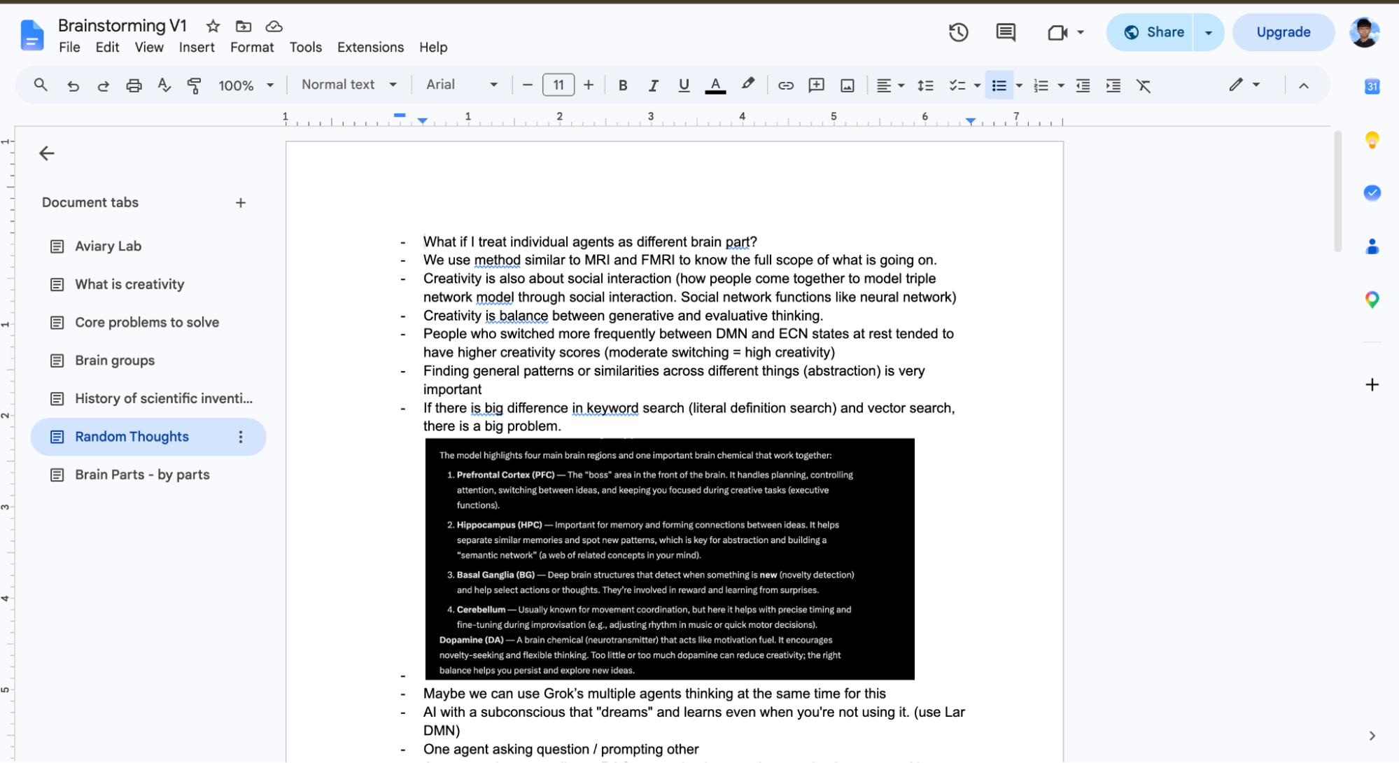
(part of my AI creativity research log)
While working on that, I thought it would be cool if I could scan my own brain to see how creativity works in my own brain! That’s how I came up with the idea to make my own EEG headset to scan my own brain. Along the way, I my friend messaged me this, which I thought was good idea.

(what my friend said)
It was a nice idea! That’s how this project started.
Overview
First thing I had to do was to make sure that I was on a budget. It wasn’t.

It costed me a lot of dollars. Yet, I discovered that organization called Hack Club funds up to $1000 of the money to teen builders. So I decided to join their program to build.
The first thing I had to do was to make a PCB board or chip for my EEG technology. It was my first time trying to make PCB. I spent the next two days watching tons of these basic Kicad videos and dived right into making one.
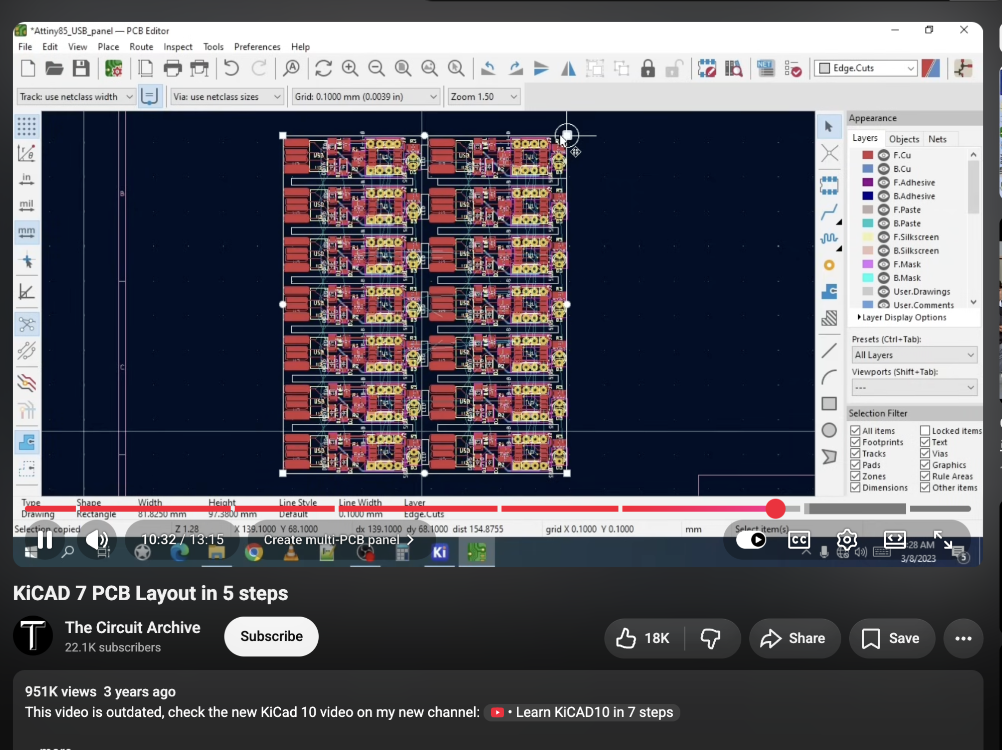
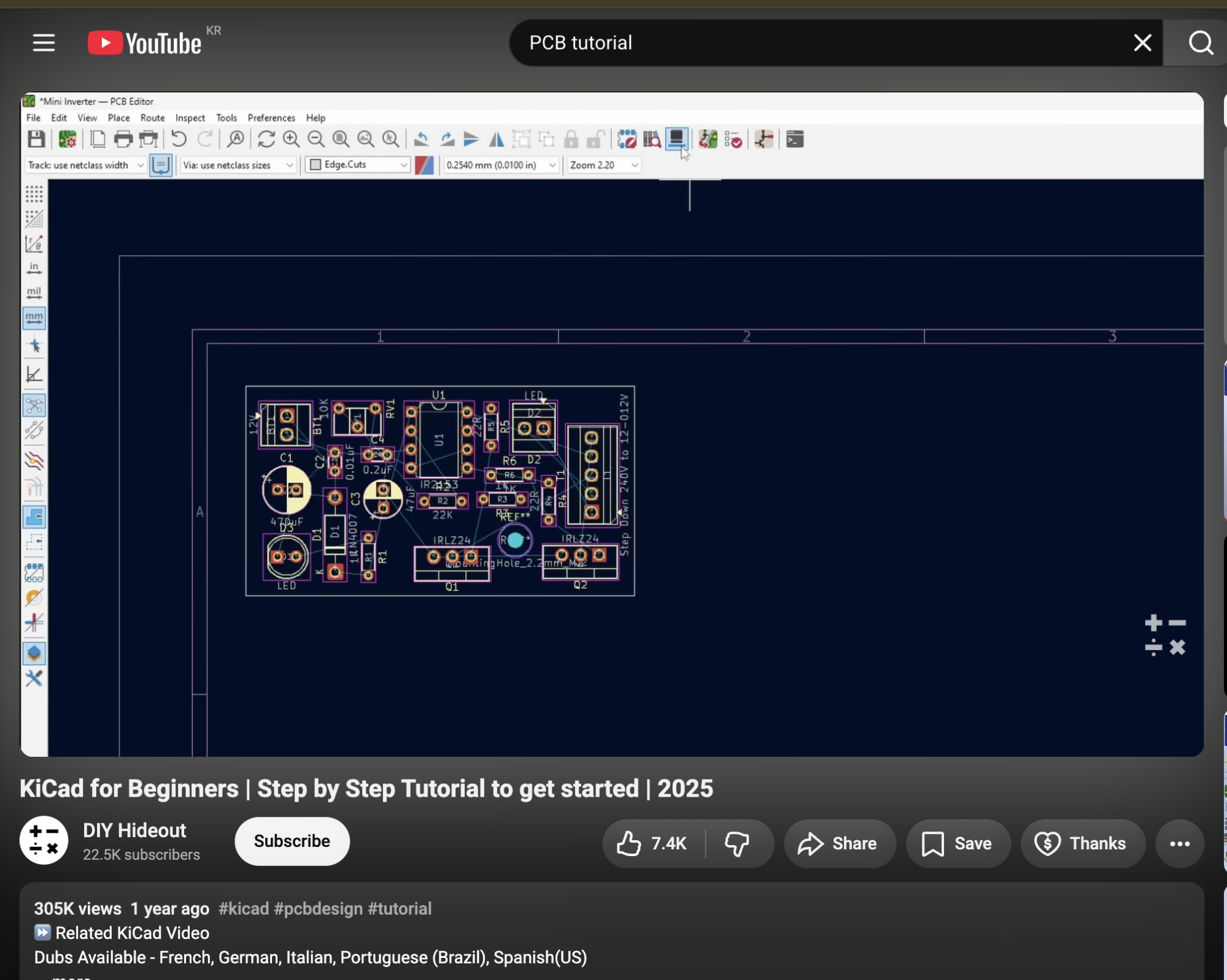
The first thing was to make something called schematic. It was easier than I thought because I can basically label things according to the data sheet of the components and add a little bit of logic suited to my use. I decided to use Kicad and spent the next 7 days making this.
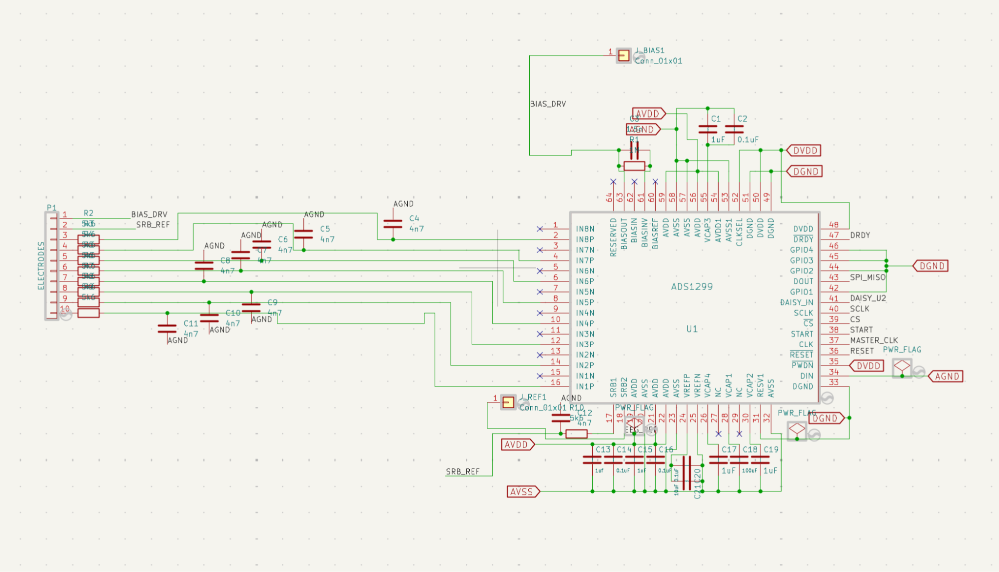
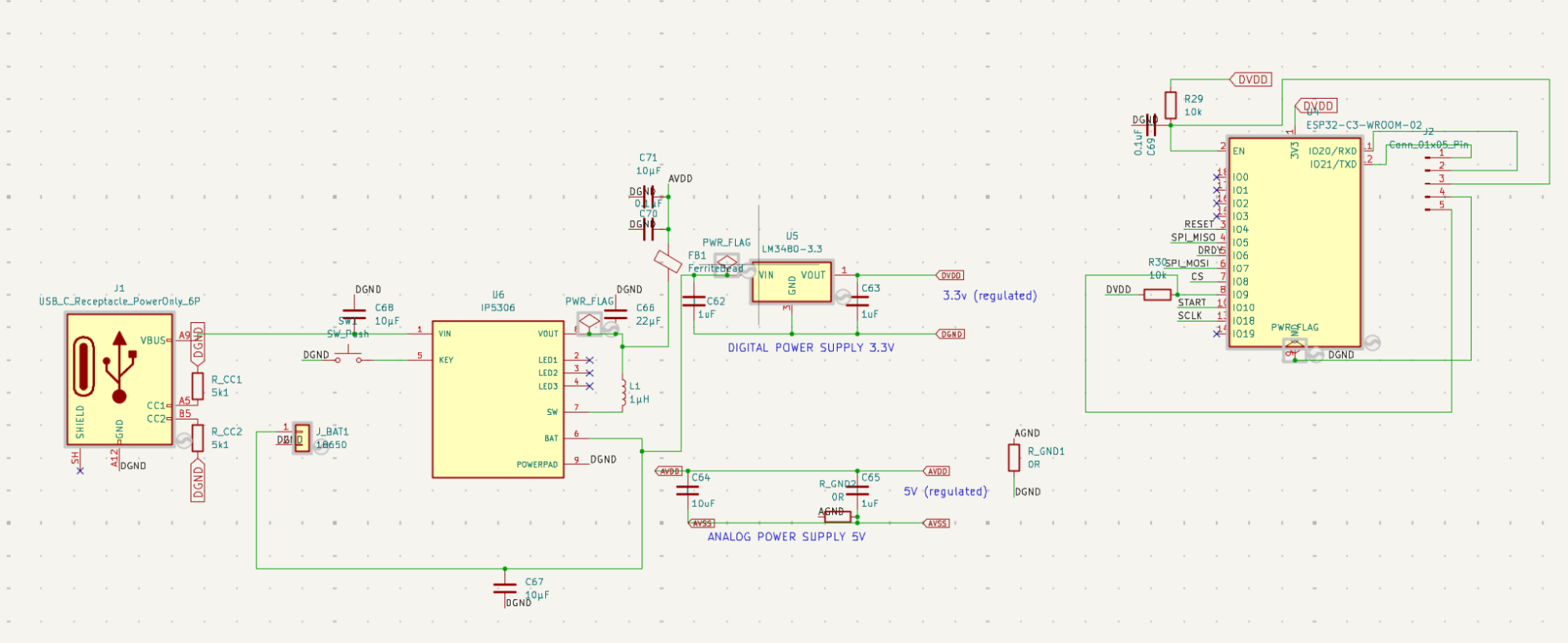
(left is ADS1299 chip while the right is power supply part of chip)
There were many failures during this process.
- I forgot to put decoupling capacitors and resistor, so I had to rewire every single wire associated with that component.
- Second, I realized that the component I was trying to use was outdated that was no longer producing. I had to rewrite the entire part again.
- Oops! I deleted the file accidentally and spent a lot of time backing up.
- I didn’t know that digital ground (power part) and analog ground (part where brain signal travels) should be separated to reduce noise.
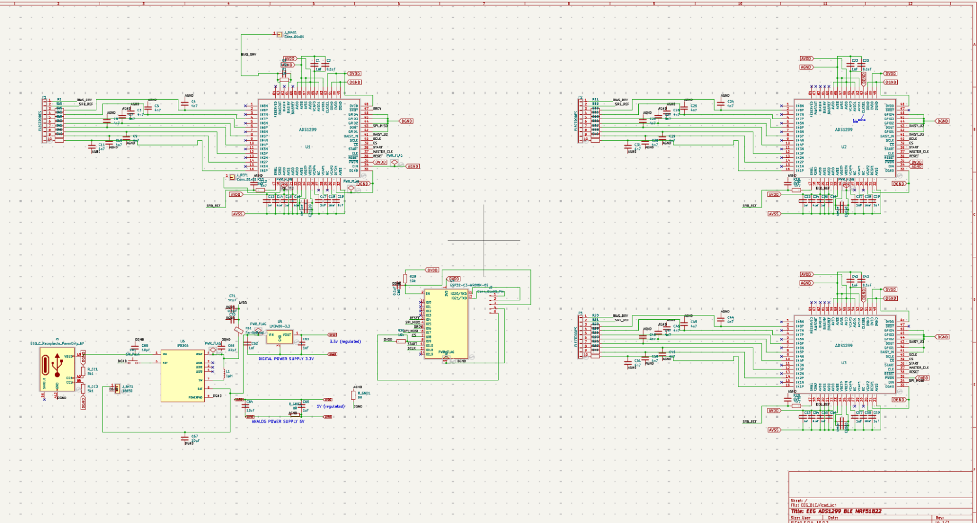
(full overview of the schematic)
After all these failures over a week and assigning footprints to each components, I could move to my PCB design.
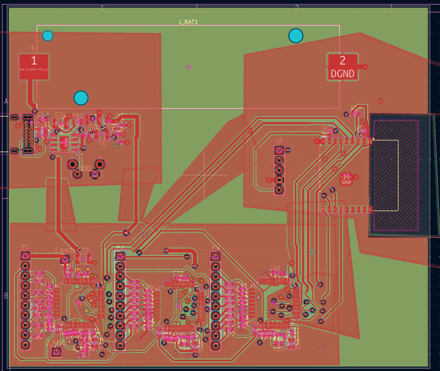
PCB designing process was craazzzy. It wasn’t hard, yet it was like solving through a maze. First, I had to place the components in the right place so that routing track is minimized for effective electricity conductivity. The key here was to place decoupling capacitor extremely close to the ADS1299 chip so that it actually decouples and reduce the noise. Then, I had to route all the traces. I had to connect route through the maze of other route that was intertwined with other wire. COMPLEX PROCESS (but i loved it). Check the image below for the final product.
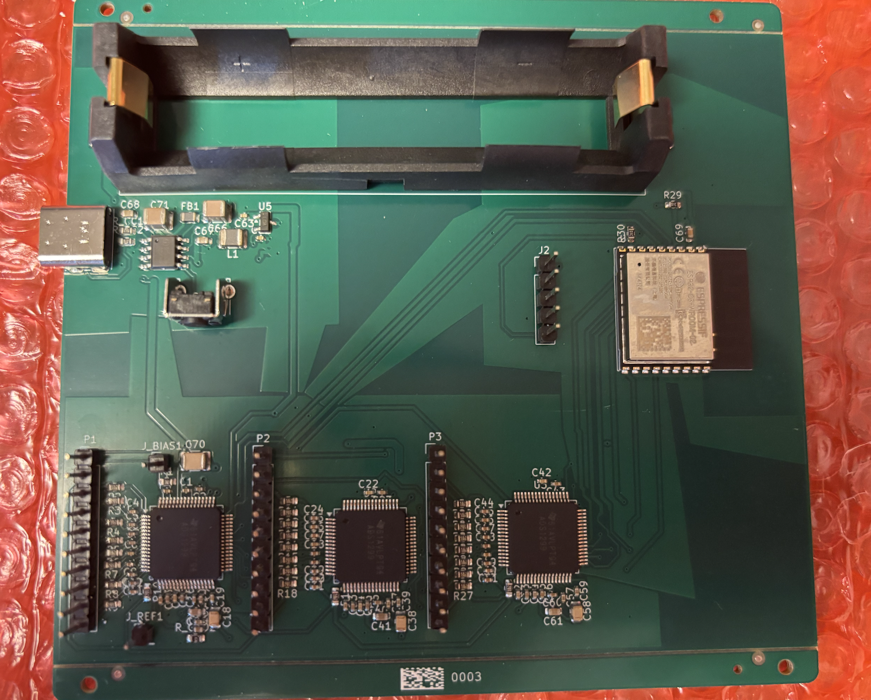
I exported BOM and component placement sheet and used JLCPCB website to order. This is how it came.
I plugged USB C cable, connected to laptop, installed arduino to write sample code to test if the PCB works and this was output.
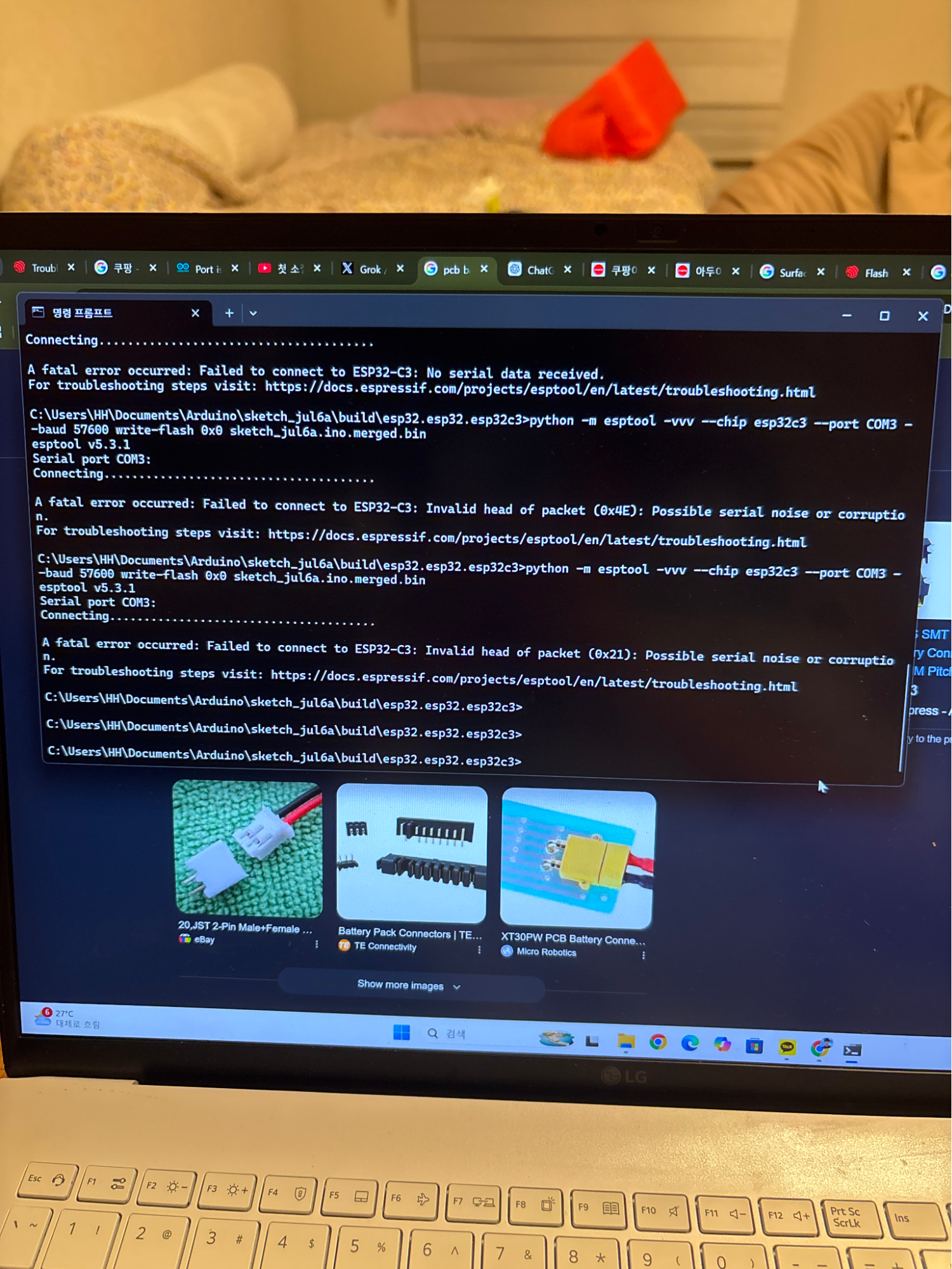
I couldn’t connect due to error occurring. The error was happening because it failed to enter flashing or download mode to download the code into it. Mistake was that I ordered raw ESP32 instead of ESP32 dev kit so it didn’t manually enter flash mode. So, I manually wired everything using dupont cable, forced it to enter download mode, and confirmed that it was actually working.
The next step was to make VR display for the helmet. Here is the thing. Building VR display takes a lot of money, which I didn’t have as a broke student. The solution I had was using this method in this paper to turn my phone into VR display. You can check the image below to see how I will turn my phone to VR display:
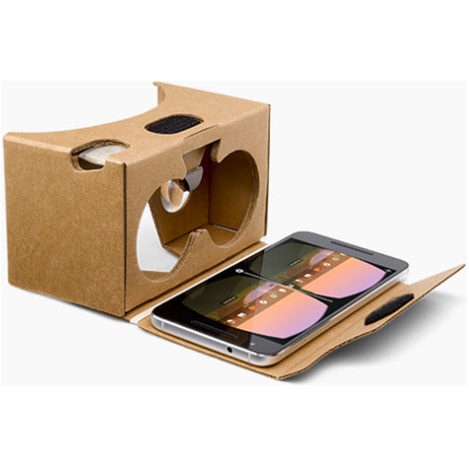
To make this, I had to order glass lens and use 3d printing to make the hardware part of the VR headset. I used onshape, CAD platform my friend recommended, to make this simple VR display design.
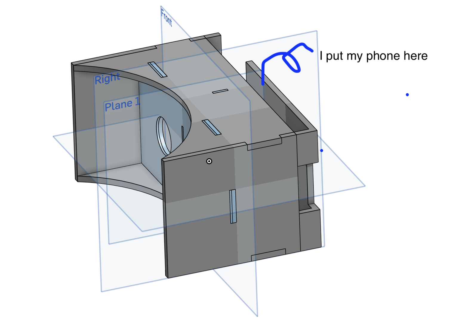
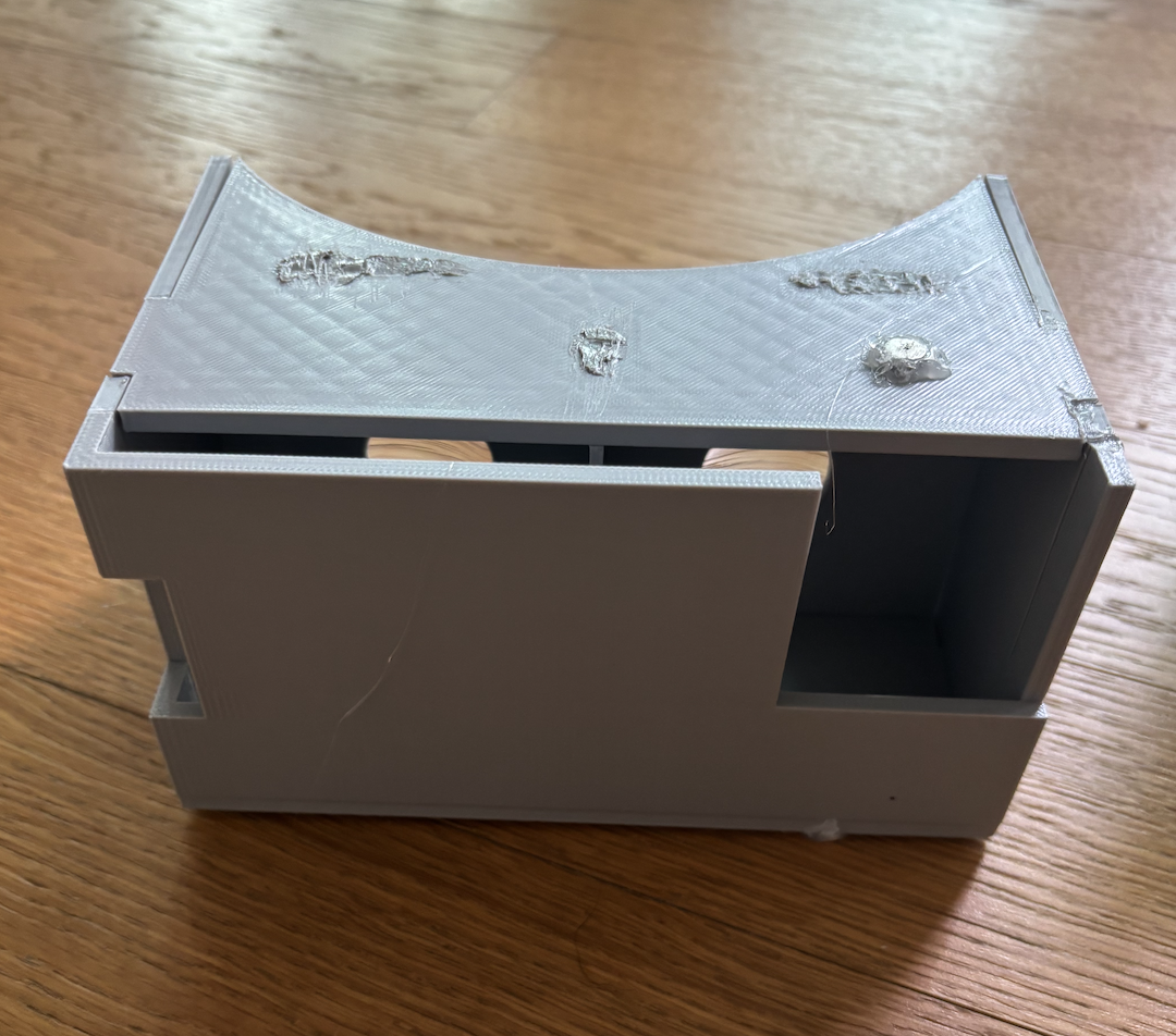
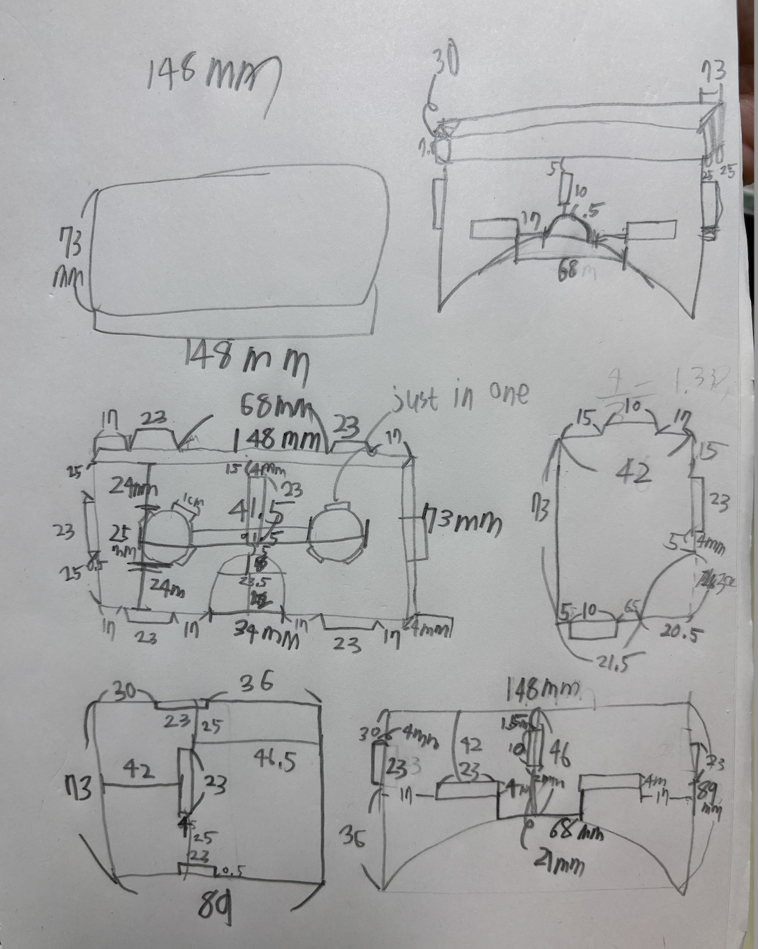
(top left is 3d model i designed and right is the actual printed product. Bottom left is the initial sketch)
Then, I will embed this thing into my helmet. After tinkering around with Blender, I made an ironman helmet and VR display embedded inside.
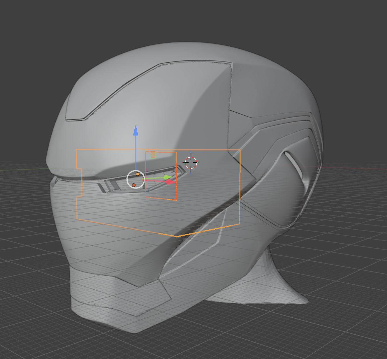
Problem: my 3d printer is small, so it can’t print the entire helmet in one go. So i had to divide helmet in to smaller parts and print like below.
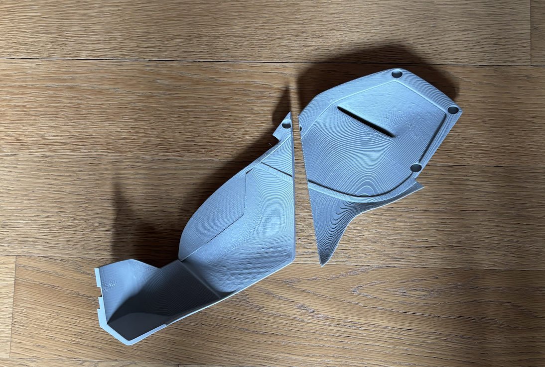
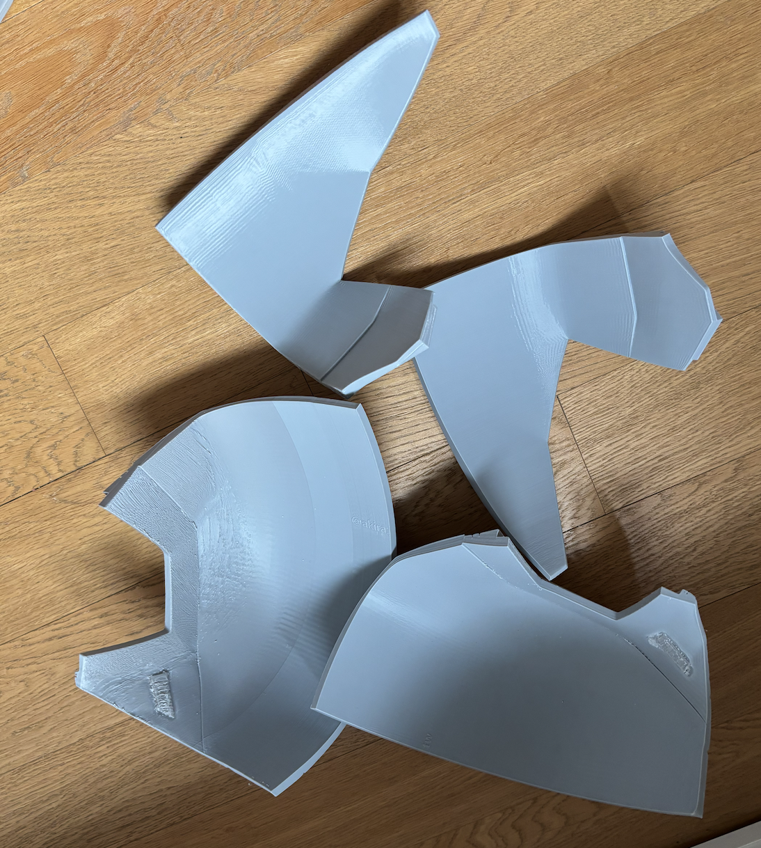
Then, I glueguned the magnet for components that should stick-and-detach. Then, I welded together the component that should permanently stick by soldering iron . Like this:
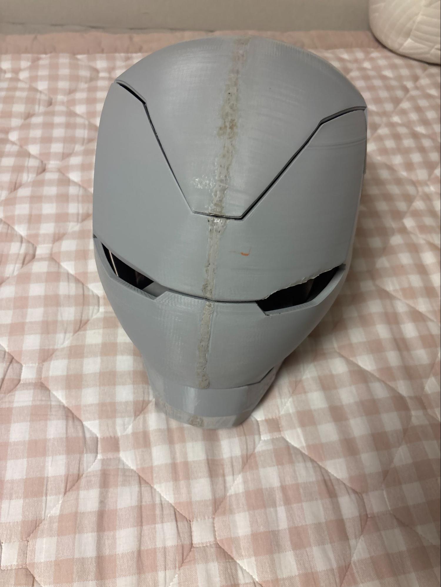
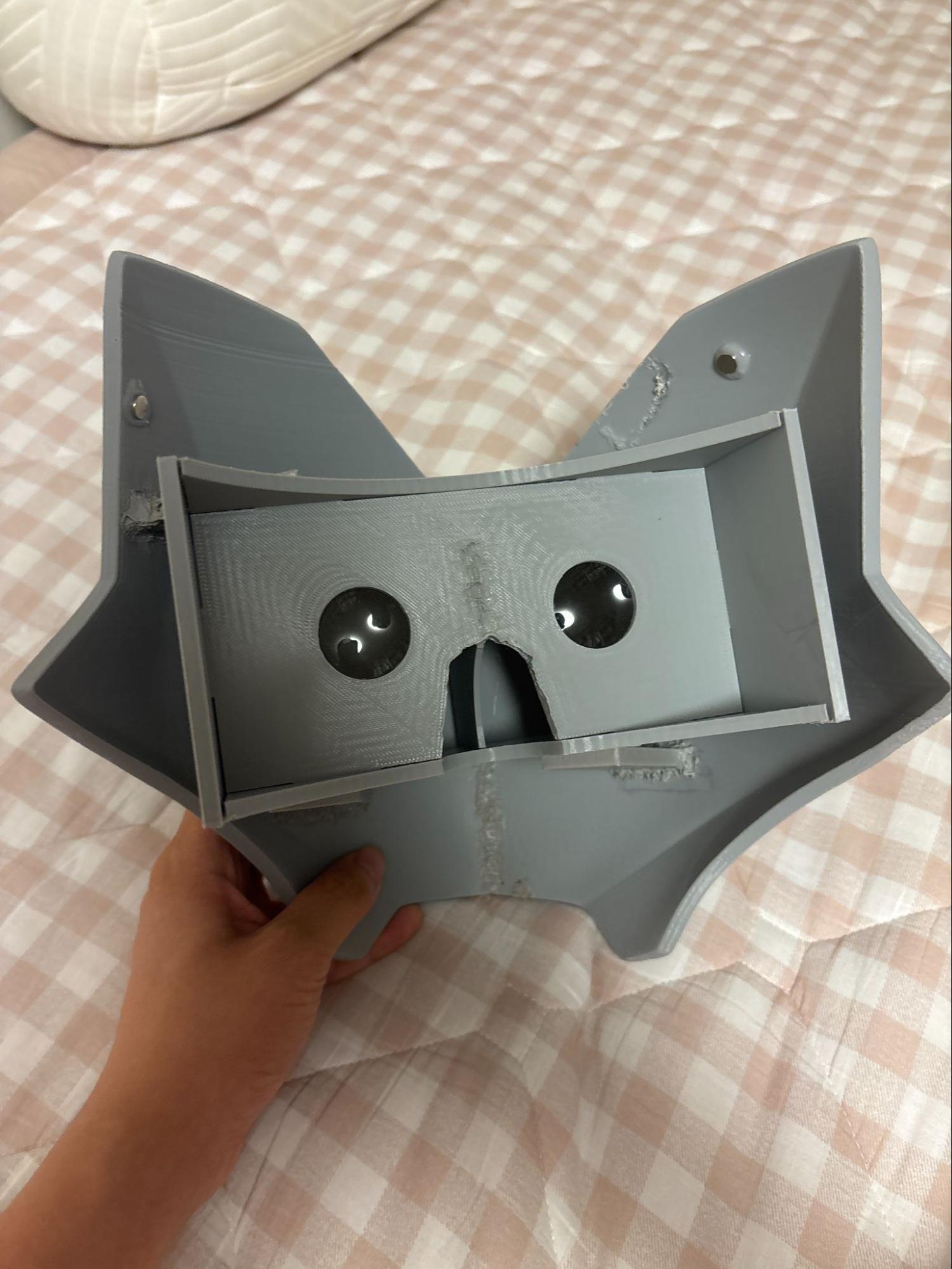
Then, I started spraying filler spray and metallic spray to give color to the helmet.
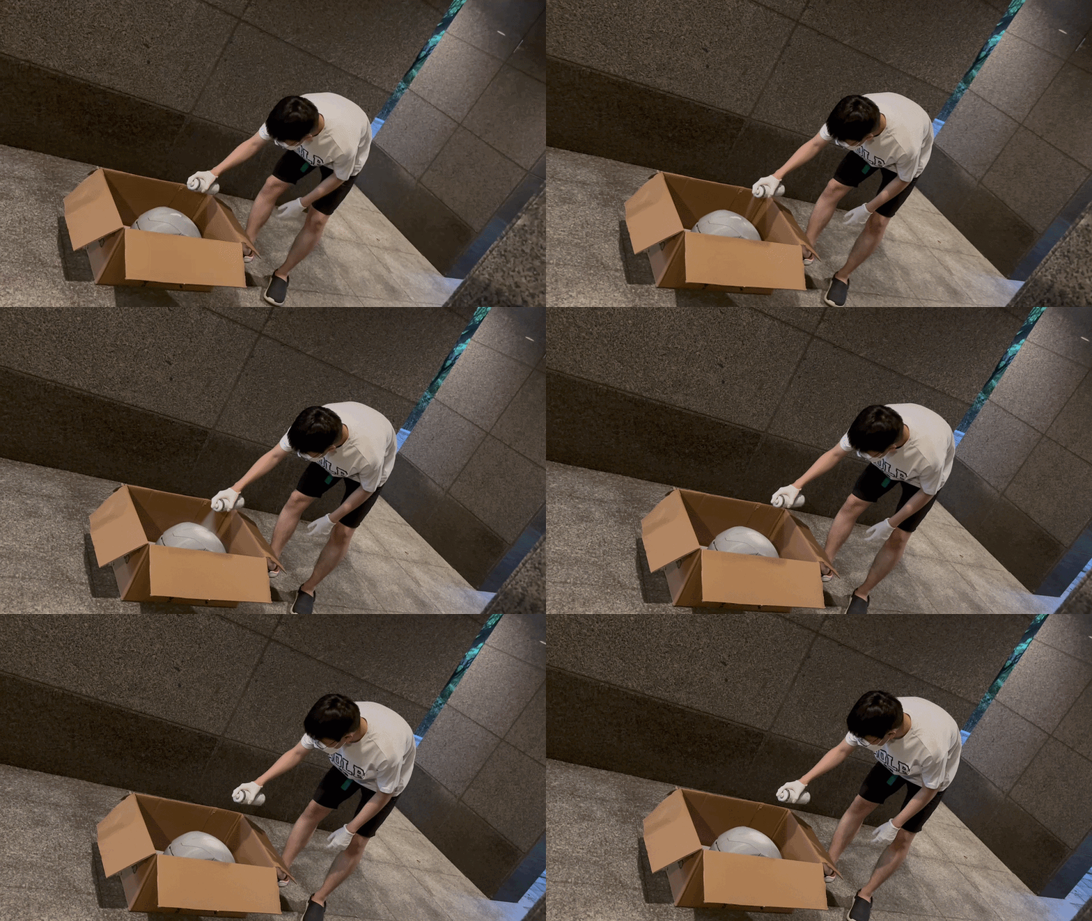
⚠️ This project isn’t fully completed. I will update the progress in a meantime ⚠️